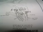
The starter gets it's power directly from the + battery cable. When you twist the key, the solenoid connection (S) gets 12 volts to crank the starter motor. The wire supplying the + side of the coil has a resistance inline that cuts down on the voltage to maximize points life. The resistance terminal (R) supplies 12 volts directly to the + side of the coil to bypass the resistance wire ONLY during cranking for faster starts.
This is how the stock points system works. Extending from the firewall engine harness connector(below the brake booster), is a calibrated length of special resistance wire. This wire does not extend all the way to the positive side of the coil. In the harness, it is joined by a wire leading from the "R" terminal of the starter solenoid, and from there, it extends to the positive side of the coil. There is a shorting switch inside the starter solenoid. When the starter motor is cranking the engine to start, the shorting switch inside the solenoid, sends battery voltage through the yellow wire to the coil positive, effectively bypassing the resistance wire. Once the engine starts, and the key is released to the run position, the yellow wire ceases to supply voltage, and voltage flows from the firewall via the resistance wire. This drops the running voltage so that point life is maximized.
To test the system for proper functioning requires a volt meter. Connect the voltmeter between the positive side of the coil and ground. Turn the ignition switch to the run position. The reading should be 5.0-5.5 volts. It is important that the ignition points be closed for this test. If the points are open, the voltmeter reading will be full battery voltage. Bump the engine over until the points are closed, and check again. Again, 5.0-5.5 volts is the normal reading with the engine stopped, ignition key in the run position, and the voltmeter connected between the positive side of the coil and ground. The second part of the functionality test requires that you pull the coil wire out of the distributor, and ground it so the engine will not start. With voltmeter connected as before, crank the engine continuously, and observe the voltmeter. The reading should jump from the previous 5-5.5 volt reading up to 9 volts minimum. If it does not, it indicates a problem with the shorting switch inside the starter solenoid, or a wiring problem between the "R" terminal of the solenoid, and the coil. This will result in hard starting when cold.