IHeartGroceries
Member
I've poured over tons of threads, read the manual and still have a few questions regarding this cockamamie Switch Pitch setup of my 67 Skylark. Just trying to get everything up and running the way it was originally intended.
I have pulled the plunger switch off and cleaned it up and determined it's functioning correctly. I also know the idle micro switch is functioning.
Firstly, I dropped the pan and strainer and find the stator solenoid wire just dangling with seemingly no solenoid. I can't even determine where should it be, because the shop manual photos are so poorly detailed. I don't see an orifice nor any threaded wells for fasteners. If indeed there isn't one, I would like to acquire one. Seems like it's impossible to find. Is there a source for them out there somewhere?
The detent solenoid is there and functions as intended.
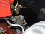
Secondly, I have determined the idle micro switch should be open at idle and closed with the slightest throttle pressure applied. Is that correct? If so, I can't determine in what way the switch is actuated by the linkage. There is no cam or anything of that nature on the clevis linkage and I am unable to make the switch engage by any other method than just pressing it by hand. In others words, throttle applied does not engage, nor disengage the switch. I have attempted to adjust its position, as the manual stipulates, but as I stated, I don't see anything which should contact the switch.
Thanks for reading!
I have pulled the plunger switch off and cleaned it up and determined it's functioning correctly. I also know the idle micro switch is functioning.
Firstly, I dropped the pan and strainer and find the stator solenoid wire just dangling with seemingly no solenoid. I can't even determine where should it be, because the shop manual photos are so poorly detailed. I don't see an orifice nor any threaded wells for fasteners. If indeed there isn't one, I would like to acquire one. Seems like it's impossible to find. Is there a source for them out there somewhere?
The detent solenoid is there and functions as intended.
Secondly, I have determined the idle micro switch should be open at idle and closed with the slightest throttle pressure applied. Is that correct? If so, I can't determine in what way the switch is actuated by the linkage. There is no cam or anything of that nature on the clevis linkage and I am unable to make the switch engage by any other method than just pressing it by hand. In others words, throttle applied does not engage, nor disengage the switch. I have attempted to adjust its position, as the manual stipulates, but as I stated, I don't see anything which should contact the switch.
Thanks for reading!