"Buick Trademark(s) used with the written permission of General Motors"

INLET DESTRIBUTION

CARBURETORS AND LINKAGE

The Series 44 will be equipped with a single dual carburetor as last year. The other Series 45, 46, 47, 49 will have a carburetion system known as compound dual carburetion employing two dual carburetors as standard equipment. Compound dual carburetion will be available on the Series 44 as optional equipment.
Compound carburetion permits higher compression ratios, greater volumetric efficiency at higher speeds, and also results in increased H.P. performance and fuel economy. The increase in H.P. on the Series 44 with compound carburetion is from 107 to 125 and the large engine from 141 to 165 H.P..
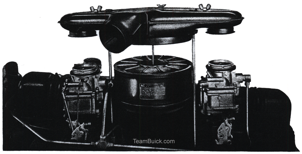
Engines equipped with compound carburetion make use of two dual carburetors mounted on one dual manifold. The outside branch of the manifold is connected to the outside barrel of both carburetors, and feeds cylinders numbers 1, 2, 7 and 8. The inside branch of the manifold is connected to the inside barrel of both carburetors, and feeds cylinders numbers 3, 4, 5 and 6. This arrangement of carburetors and manifolds makes it possible for either front or rear carburetor to feed to all eight cylinders.
The front carburetor is complete and includes a float system, main metering system, accelerating pump, power by-pass system, idling system, starter switch and automatic choke. The rear carburetor contains only a float system, idling system and main metering system.
When the engine is idling and up to approximately 22 M.P.H. part throttle, the idling systems of both carburetors are in operation.?
A damper valve assembly is used between the rear carburetor and the intake manifold. This valve is held in the closed position by an offset weight and serves to govern the operation of the rear carburetor. The flies in the damper valve assembly are not a tight fit and for this reason the idling system of the rear carburetor will operate with the valve in the closed position.
The throttle rods and levers are so arranged that the throttle of only the front carburetor is opened until a position is reached which will give approximately 75 M.P.H. on part throttle. Up to this point of opening only the front carburetor operates, except for the idle system of the rear carburetor. Additional movement of the accelerator pedal will start to open the throttle of the rear carburetor. Opening of the rear carburetor throttle valve allows intake manifold vacuum to open the damper valve and bring the rear carburetor into operation. When the throttles of both carburetors are fully opened, the front and rear carburetors will feed equally.
If the accelerator pedal is fully depressed at low speed, only the front carburetor will operate until the manifold vacuum is sufficient to open the flies of the damper valve assembly. This will begin to occur at approximately 15 M.P.H. and will reach the wide open position at appositely 35-40 M.P.H. if the accelerator is held fully depressed.
CARBURETOR TO MANIFOLD GASKETSA new hard fibre gasket is used between the carburetor and the intake manifold on all Series. This gasket is the same on all Series because all carburetor flanges are of the three bolt type as formerly used on the Series 44, 45 engines.
On engines with a rear carburetor, this heavy gasket is installed between the damper valve assembly and the intake manifold. A thin gasket is used between the damper valve and the carburetor.
Gasoline recommendations are Regular Gasoline for the Series 44 with single dual carburetion, and a Premium Fuel for all engines equipped with compound carburetion.
CARBURETOR IDENTIFICATIONThe 1941 cars make use of five different Stromberg carburetors. Each carburetor is designed and calibrated for the engine size, and position on the manifold where it is located. There are slight but important differences between the various carburetors. Even though they are of the same model designation, one must never be interchanged with the other.
The Series 44 engine is standard equipment with a single dual carburetor the same as used in 1940, including external vent to the float chamber. All carburetors both front and rear, used on compound equipped engines, have balanced float chambers with internal vents.
The following table shows the various Stromberg Carburetor models used on all Series:| Series | Carburetor Model | Carburetor Code No. |
| Series 44 Standard | AAV-16 | 7-37 |
| Series 44 Compound (Optional) Front Carburetor and Series 45 Compound Front Carburetor | AAV-16 | 7-42 |
| Series 44 Compound (Optional) Rear Carburetor and Series 45 Compound Rear Carburetor | AA-l | 7-43 |
| Series 46, 47, 49 Compound Front Carburetor | AAV-16 | 7-39 |
| Series 46, 47, 49 Compound Rear Carburetor | AA-l | 7-41 |
HEAVY DUTY AIR CLEANER AND EXHAUST

NEAT CONTROL VALVES

All Series engines are equipped with Heavy Duty Air Cleaners; the regular air cleaners are not available.
The Series 44 engine equipped with the single dual carburetor, uses the same type air cleaner as in 1940. The air intake and external float chamber vent is also the same.
A new type Heavy Duty Air Cleaner is used on all engines with Compound dual carburetion. This air cleaner is the same on all Series. The new air cleaner is equipped with an air intake which takes air from in front of the radiator core. Cooler air serves to increase volumetric efficiency of the engine and assists in reducing spark rap.
With the air intake located in front of the radiator core on Compound carburetion jobs, it is obvious that the air pressure changes with car speeds. To offset any effect on carburetion as these changes occur, all carburetors used with Compound equipment have an internal float bowl vent to obtain balance between the carburetor float chamber and the air intake.
To afford additional assurance of balance between the float chamber and the air intake system, gaskets are used between the air cleaner assembly and the carburetor air horns. The front carburetor accelerator pump is also sealed with a rubber syphon.
AIR INLET SCREENEngines equipped with Compound carburetion are provided with a 3" diameter flexible hose to bring air from ahead of the radiator core. A coarse mesh screen is provided at the inlet hose to prevent large insects and other material from entering the system.
The screen may be removed by removing the sheet metal panel from the top of the grille. Remove attaching screws and slide the screen down from behind the rain baffle.
EXHAUSTThe Series 44 engines using one dual carburetor, are equipped with a one-piece manifold the same as used in 1940.
All Series engines equipped with Compound carburetion have exhaust manifolds made in two separate sections. Both front and rear sections are equipped with thermostatically controlled heat valve assemblies. The heat valves are part of the exhaust manifold and are not serviced separately except for thermostatic springs. The heat valves use a new anti-rattle spring arrangement which prevents valves from rattling in either open or closed position. MANIFOLD HEAT CONTROL VALVE ADJUSTMENT
On single carburetor Series 44, the adjustment should be made as formerly, with the valve in the closed position.
Both anti-rattle springs must be adjusted on Compound carburetor equipped engines. On this equipment the anti-rattle should be adjusted so that the control valve will not rattle when the valve is in the fully opened position. This adjustment will automatically set the valve for the closed position.
The adjustment can be made regardless of whether the engine is hot or cold.
The adjustment is made by bending the clip to which the spring is attached. This clip should be bent so as to hold the valve 1/8" off its seat in the wide open position.
EXHAUST PIPE ASSEMBLY AND TIGHTENING (COMPOUND CARBURETION)The front section of the exhaust pipe, on engines equipped with compound carburetion, is dual or "Y" shaped at the front end. The front section fastens to the rear section just below the alignment flange. A special gasket is used at the alignment flange and should be assembled with the side that has the longest taper "down".
This type of exhaust pipe should be installed as follows, to prevent exhaust leaks and failure of parts:
1. Assemble loosely at all points to obtain alignment.NOTE TO INSTRUCTOR:
2. Tighten the rear flange assembly to the rear section of the exhaust manifold.
3. Tighten the clamp that connects the front and rear sections of the exhaust pipe together, and joint at the front end of the muffler.
4. Tighten the front flange assembly to the front section of the exhaust manifold.
5. Tighten the alignment flange.
The instructor should explain the difference in the adjustment of the heat control valve between Standard and Compound Carburetor equipped jobs. Make sure that mechanics understand that the Series 44 Standard Carburetor equipped jobs are adjusted in the closed position, while on the Compound Carburetor equipped jobs the heat control valves are adjusted in the wide open position.
Incorrectly adjusted heat control valves will result in rattle and the incorrect amount of heat being applied to the intake manifold.
Point out the importance of correctly assembling and tightening the exhaust pipe on Compound Carburetor equipped jobs.
HEAVY DUTY OIL BATH AIR CLEANER
As previously mentioned, all Series are equipped with Heavy Duty Oil Bath Air Cleaners. These units will not be filled at the Factory. It is, therefore, important that Dealers arrange to fill these units with the proper grade of oil, to the correct level, at the time of the New Car Inspection. The Heavy Duty Oil Bath Cleaners do not operate as a cleaner unless they are filled with oil. This point, therefore, should not be overlooked.
Dealers in certain localities have not been receiving cars with this equipment; therefore their mechanics will not be familiar with the filling and servicing of these cleaners. These Dealers should make sure that all mechanics are made familiar with these Heavy Duty Air Cleaners.
It should be pointed out that under no circumstances should oil be applied to the cleaner element.
| NOTE TO INSTRUCTOR:
Instructor should emphasize the importance of filling Heavy Duty Oil Bath Air Cleaners on all jobs during the New Car Inspection, and to make sure that the gaskets between the carburetor and air cleaner are in good condition, and that the thumb screw is tightened when assembling the cleaner. |
- Disconnect Rear Throttle rod.
- Hold choke in closed position and fully depress accelerator against floor mat (deloader spring extended).
- Adjust front throttle at trunnion until it is just wide open.
- With accelerator against floor (deloader spring extended) adjust rear throttle rod trunnion until throttle is just wide open. This will provide correct initial opening of rear carburetor.
COMPOUND CARBURETION
THROTTLE LINKAGE ADJUSTMENTS1 Disconnect the rear throttle rod at the carburetor.
2 With the choke in the cold position, depress the accelerator pedal against the floor mat. (Deloader must be in operation to exert normal load on the throttle rod when accelerator is depressed.)
3 Adjust trunnion on throttle rod until throttle valve is just wide open (with trunnion in lower hole in throttle lever).
4 With the accelerator fully depressed against the floor mat (deloader spring extended), adjust the trunnion on the rear throttle rod until the throttle valve is just wide open (with the trunnion in the upper hole in the throttle lever, or hole nearest the center of the throttle shaft).
| NOTE TO INSTRUCTOR:
Instructor should make sure that mechanics are thoroughly familiar with the adjustment of the carburetor linkage on the Compound carburetor equipped jobs. Any error in making the adjustment will seriously affect economy and performance. |

1. Back off both idle speed adjusting screws until throttle valves are fully closed, and the ends of the adjusting screws barely contact the thin section of the cold idle cam on the front carburetor, and the throttle body on the rear carburetor.
2. Turn the idle speed adjusting screw in 3/4 turn on both carburetors. This will give an idle speed of approximately 7 to 8 M.P.H. in high gear.
3. Turn in the four idle mixture adjusting screws until they are just seated in the throttle valve body. (Do not force screws on seat as this will damage the screws.
4. Turn each idle mixture adjusting screw out one turn.
5. Start the engine.
6. If the mixture is rich, turn all four screws in equally until best idle is obtained, and turn all four screws out equally if mixture is lean. If the idle speed needs changing, turn each idle speed adjusting screw in or out the same amount until the desired speed is obtained.
If a vacuum gauge is used when setting the idle mixture, the idle should be set to read 1" less than maximum reading.
If difficulty is encountered in obtaining a satisfactory idle, a check should be made to see that the gaskets between the carburetor and air cleaner are in good condition, and that the air cleaner is properly seating on the gaskets. A check should also be made to see that the rubber seal on the accelerator pump is in good condition.
Depress the accelerator pedal just far enough to engage the starter.
Depress the accelerator to the floor and hold until the engine fires regularly.
The vacuum piston setting on the Series 44 with Standard carburetor, is the same as in 1940.
The Series 45, 46, 47, 49 using Compound equipment, is changed to use a #5 Drill between the air horn and the choke valve when setting the vacuum piston.
On engines equipped with Compound carburetion, the "V" mark should line up with the projection on the thermostat housing. Series 44 with single carburetor should be set one notch lean.
| NOTE TO INSTRUCTOR:
As the procedures for adjusting the idle speed and idle mixture are entirely different than in the past, these points should be gone over very carefully to make sure they are understood. Point out the importance of checking the gaskets between the carburetors and air cleaner, and the rubber seal on the accelerator pump of the front carburetor, where difficulty is experienced in adjusting idle mixture. |