"Buick Trademark(s) used with the written permission of General Motors"

Looked for a performance distributor for your Classic Buick engine lately? Sure isn't like a chevy, they can have anything they want...:(
Depressing, isn't it?
A nice tight running distributor is a "must" for a performance engine and an advantage for any engine.
If you have ever watched a slightly worn distributor bounce the spark around on a scope you will appreciate how much the spark timing is affected. Even with a reasonable scope pattern, it is disappointing to pull a distributor down to find the shaft uncomfortably worn. "They" said these were lubricated bushings?! I think there it may be possible to do some modifications that would help the bushings last, but I like the idea of running the shaft on bearings! So here goes.
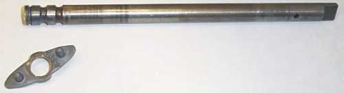
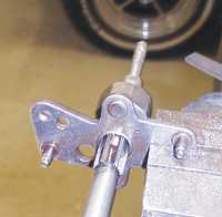
I decided to take the original points distributor and turn it into what I want from a distributor! I wanted breakerless and bearings. Here you see the original shaft with the advance cam removed. It is silver soldered to the shaft.
I won't go into basic disassembly here, because if you can't figure out how to take it apart, you are probably going in over your head on this one.
Sorry guys, you are going to need a lathe, or a friend with one. A lathe is absolutely necessary, and while you may be able to simply grind the flat on the shaft, a mill would be much nicer.
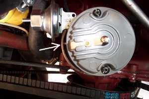
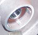
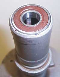
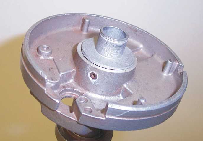
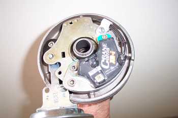
The bearings I chose to use were NSK R8 sealed bearings. They had a .500" ID, 1.125" OD, and were .312 wide.First project was to fit the bearings into the distributor. As you can see some of the ribs which held grease for the bushings are still left to hold the upper bearing. I sank the upper bearing about .300" to allow the carrier for the advance plate to fit nicely above the bearing. The lower bearing is just sunk into shaft far enough to hold it securely.
I used good old 4140 shafting for all pieces.
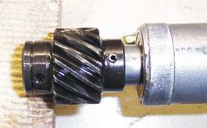
The shaft was .500" to fit the bearings. The end was relieved to accept the advance cam. The cam was then silver soldered on. Two reliefs to take grease for the advance plate were machined into the shaft just below the cam. These are not critical measurements, and as long as the resemble the originals will be just fine. (you can see the grooves in the top picture)
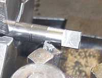
With the top of the shaft finished, we moved to the lower end. The original shaft was about .491 in diameter. The new shaft was turned down to .491 to accept the gear on a slip fit.
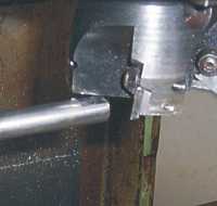
The flats to fit into the pump drive were machined, then a bevel was ground on the end, similar to the original to make sliding into the pump shaft easier.
When it came to the advance plate, I made the hole .5032", enough to safely clear the shaft.
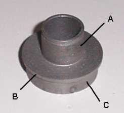
A...The outside diameter was made .645 and the height was .625, a small groove was cut to accept the advance plate retaining ring.
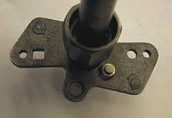
B...The height of B was made to be .065" with a diameter of about 1.250". The top of the distributor housing was cut level above the bearing to allow for this. This dimension is relevant to the depth of the upper bearing in the distributor and the relief of about .300" that you left to accept this piece.
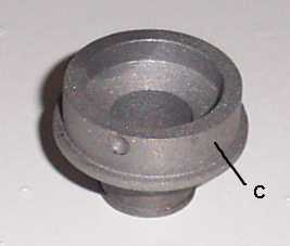
C...This part should be the diameter of the bearing, 1.125" and the .300" height allowed above the bearing. The small set screw hole was drilled in when the set screw was drilled into the housing.
The bottom was drilled with a 1" drill to allow the part to clear the inside of the bearing while resting on the outer race.
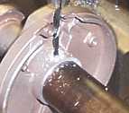
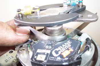
This was the easiest way I could think of to get the pickup as close as possible to the cam but know it wasn't touching it (those were the instructions!). The cam may not be regular all the way around so rotate it with the feeler gauge in place.
After the bushing was installed I found that the movement allowed was about .080" yielding the 15 degrees of advance mentioned. The original hole measured about .345", I lengthened it to about .375" and reinstalled the distributor. I got about 18 degrees. I then lengthened it to a big .385" and got my 20 degrees.