:bana:
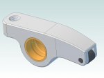
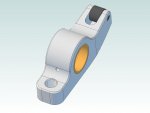
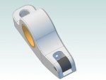
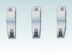
I did it. Being a cut price person in a low budget land I couldn't even consider using custom roller rockers for a street cruiser. But knowing that the 263 had very little valve lift increase available at the cam after a regrind that modified the duration and lobe separation, I was force to look to the rockers for any significant increase in gross lift at the valves. As the lobe centers get moved together and any increases in duration get applied, significant amounts of the ramps get ground away along with the stock lobe peaks while most of the base circle disappears. The 263 cam will only net about .270 inch lift with only slight increases in duration and increased overlap. When I looked at the rockers, then drafted to scale their dimensions on graph paper, I discovered that depending on the geometry caused by the adjusters position, the ratio varied between 1.42:1 and 1.53 at the other extreme. I resolved to increase the rocker ratio by offset boring and rebushing each rocker and the stands 1/16 inch closer to the push rods. This change would results in a new ratio of 1.66:1 when adjusted to the optimum geometry according to the math. The first thing I had to do is make two jigs to hold the rockers for offset boring in my Maximat7 mill. After the rockers were bored ,the bronze bushings were pressed in with locktite and all the oilling holes were redrilled. The new holes in each bushing were then deburred and champhered with a small ball cutter on a Dremel handpiece for more assured oiling To complete the mod the stands had to be cut down so that the shaft centerline sat perpendicular to the valve at half lift. The gross lift at the valve is now .470 inch and while not much by modern standards is a very good improvment for a 263. After the assembly was installed and thoughly checked out I dicided to make a strap girdle to run the complete length of the rocker assembly. I remilled the tops of all the stand to assure exactly equal height and a flat surface. I made spanner straps that sandwiched the stand's with through bolts and pieces of 3/8 inch black pipe on the pushrod side of the stands. These spanners were made from 1/4" X 1" stainless steel. I then cut and tigged a long strap of the same stock to each of spanner straps. The last thing to complete the process was to hygrade several sets of pushrods from solid lifter engines. These needed to be cut down to the optimum length fit the lower adjuster position. Within a few cuts and trims I arrived at the the correct length for the optimum location of the adjuster bolts. Each trim required pulling the pushrod tips off their tubes turning off a few thousandths and then repressing the tip back on. Much of this project was tedious repetition ( 16 times everything), the boring, pressing, turning, very time consuming. A couple months of after dinner shop time. On the plus side, low cost. Approximately $80 for tooling for the boring; $60 for bushing stock; about a $100 for the stainless; everything else came from the junkbox. The engine is up and running, installed in our 49 Sedanet SUPER, just waiting for spring and dry roads to see how well the new motor really does.
I hope this will bring some insight to how to make a major improvment to any of the Buick straight eight.
Best Regards to all that make this a great and useful website. KB. aka telekenfun.