Been doing some str8 8 design work

dlomshek

Member
Lately I've been thinking a lot about some posts concerning the need for a new cylinder head design for the 320 ci straight eight.
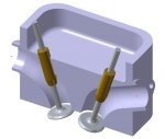
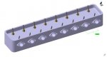
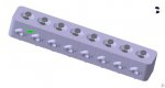
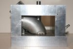
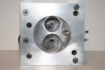
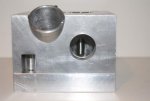
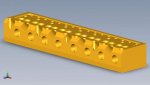
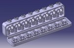
Attached is a starter drawing of a cross-flow head with individual intake and exhaust ports. The compustion chamber has been redone as a shallow hemi type with shallow valve angles of 17 degrees to the vertical.

I teach Computer Aided Design, at the state university, using CATIA.


David Lomshek
Pittsburg, Kansas
 

Attachments

  • Cylinder Section SMALL.jpg
    Cylinder Section SMALL.jpg
    17.8 KB · Views: 36
Another photo of some straight 8 head design

Here is another shot of some of my tinkering with a new straight 8 320ci cylinder head.

David Lomshek
Pittsburg, Kansas
 

Attachments

  • Cylinder Head Completed-1.jpg
    Cylinder Head Completed-1.jpg
    13.9 KB · Views: 41
  • Cylinder Head Completed-3.jpg
    Cylinder Head Completed-3.jpg
    12.4 KB · Views: 41
Last edited:
Looks good. We need one for the 248/263 as well. Ever look at the 15 degree VW v6 cross flow head design?
 
Both pushrods have to come up the same side of the engine if you are going to use the original block.
 
Both pushrods have to come up the same side of the engine if you are going to use the original block.


time to convert to OHC and just keep a dummy cam in the block to run the oil pump or whatever else is going on. :laugh_4:
 
Both pushrods have to come up the same side of the engine if you are going to use the original block.

That can still be done using an exotic rocker arm assy, roller cam, roller tipped rocker arms, needle bearings on the rockers, using a hardened rocker arm shaft or stud mounted rocker arms. A lot depends on the location of the spark plugs...
 
That can still be done using an exotic rocker arm assy, roller cam, roller tipped rocker arms, needle bearings on the rockers, using a hardened rocker arm shaft or stud mounted rocker arms. A lot depends on the location of the spark plugs...

So far I haven't decided if it's worth the effort to go all the way to OHC or not. At this stage I'm just exploring options and doing a lot of thinking. Pretty soon I probably need to buy a complete 320 engine to analyze.

One of the things I am pondering is if a head can be produced in two pieces. Upper and lower halves. This would allow all of the inner details, like water passages, to be milled with a CNC mill. This eliminates the need for cores. Problem is I would not want to bolt the two halves together. I'm looking for some furnace brazing process that would allow the two parts to be joined into one.

A number of years ago some special flathead heads were produced as two halves but the two pieces were bolted together then. Obviously flathead heads are much simpler than OHV ones.

I'm open to any and all ideas; let me know the opinions out there. Not sure where this is going but it's a very interesting design project for me.

Dave Lomshek
Pittsburg, Kansas
 
well, you can try a "pentroof" combustion chamber, like the nailhead, which is really a grunt type engine design, like most Buicks.Lots of lo to midrange power. Actually the nailhead is half of a pentroof design used usually with OHC designs. Pushrods could be used with by using wierd monkey motion designs,[a la V8-60 arduns.] If you want to see a wild Buick engine design find a cutaway of the 1951 Lesabre engine! It shows that Buicks engineering wasnt behind the times.
 
Last edited:
pentroof alum head V8, 1951 Lesabre

I found an article on Buick history in the April 78' issue of cars n parts. It was about the 1951 Lesabre concept car,
which was driven by the head of engineering for years after.
Its working concepts used in many of the future GM cars today. The engine was an aluminum 215 inch V8 square bore n stroke, carbed,dual fuel [gas n alcohol] blown, 2 valve , pushrod , pentroof [simular to hemi]alum heads! 335hp 388#torq, 10.5-1, 3 ring popup pistons, and tested at 140mph on Buicks test track. The article has the cutaways but i havnt been able to copy it up. The whole car has almost all the design features of todays cars, tilt/tell steering wheel, ball joint susp, etc, etc, I,ve never seen an engine like it, they sure were holding back on us in 1951!
If we had just a pentroof combustion chamber like the naihead in our straight 8,s, they would be twisting axles.
 
Last edited:
One of the things I am pondering is if a head can be produced in two pieces. Upper and lower halves. This would allow all of the inner details, like water passages, to be milled with a CNC mill. This eliminates the need for cores. Problem is I would not want to bolt the two halves together. I'm looking for some furnace brazing process that would allow the two parts to be joined into one.

Dave Lomshek
Pittsburg, Kansas

Simply produce the 2 halves with beveled edeges around the perimeter of the two mating halves. Place them in a jig and TIG weld the 2 halves together along the perimeter. The clamping action of the head bolts can provide enough force hold the interior sections together.
 
well, you can try a "pentroof" combustion chamber, like the nailhead, which is really a grunt type engine design, like most Buicks.Lots of lo to midrange power. Actually the nailhead is half of a pentroof design used usually with OHC designs. Pushrods could be used with by using wierd monkey motion designs,[a la V8-60 arduns.] If you want to see a wild Buick engine design find a cutaway of the 1951 Lesabre engine! It shows that Buicks engineering wasnt behind the times.

Here's a new combustion chamber shape with valve locations more amenable to pushrod activation. Still just playing around with chamber shapes and valve locations. For the present I'd like to stick with pushrod use.

Dave Lomshek
 

Attachments

  • New Combustion Chamber Design.jpg
    New Combustion Chamber Design.jpg
    15.1 KB · Views: 15
263 Head

How about a cylinder head that still maintains the resemblance of the straight 8 (all ports on the driver side with spark plugs on the other) symmetrical port design with 45 degree intake port angles. It will fit a stock block using the stock push rod location and stock valve cover. Attached are pictures of a one cylinder model and a drawing of a complete head.

Paul Muller
Spokane WA.
 

Attachments

  • MockHead2.jpg
    MockHead2.jpg
    20.5 KB · Views: 21
  • MockHead3.jpg
    MockHead3.jpg
    17.9 KB · Views: 19
  • MockHead5.jpg
    MockHead5.jpg
    19.9 KB · Views: 26
  • MockHead6.jpg
    MockHead6.jpg
    18.9 KB · Views: 21
  • Buick Cylinder Head.jpg
    Buick Cylinder Head.jpg
    14.8 KB · Views: 34
if a head can be produced in two pieces. Upper and lower halves

I noticed your idea was identical to one I had. I presented it to Chiefweasel on Webrodder website forum:

------------------------------------------------------------------
Hi------I'm new here but old. What do you think of the possibility of machining an aluminum head for 235-261 using modern head flow principles, as a two-piece head split horizontally so the water passages can be made, joined together with an o-ring seal(s). Would that be feasible, or would it require cubic money? Computer aided machine tools seem to be able to do remarkable things now.
------------------------------------------------------------------

He replied:

------------------------------------------------------------------
Well... Locally there is a guy who has machined some Flathead Ford heads exactly as you describe. But then he also has machined a dual overhead cam four-valve Hemi head for a Model B Ford and another one that is a single cam head for another banger engine. So it certainly can be done.

However, as you say, it takes a LOT of time and no small amount of money to do this. I have no idea how many hours Dean put into those heads but if you see the head you'll know it was a major effort.

3 pics on his post

I tried to add the pics, but can't figure out how to do, so try this link to see pics of heads he is talking about.

http://webrodder.com/phpBB3/viewtopic.php?f=2&t=3570
 
Water passages

Instead of making a 2 piece head for the sake of machining water passages
machine all the material for water passages by way of the top of the head as though you were strip mining. Leave a small shelf around the inside edge to support a top cover and round dowels (around ¾ inch in diameter ) where the valve guide holes will be. The round sections will protrude through the top cover. Weld the cover in place around the outside edges and protruding dowels using a deep enough V groove for penetration.
Just be aware that if you are using a T6 temper alloy the welded regions will lose the temper and you may wish to have the head re-heat treated.

Since aluminum conducts heat fairly well if there is room to drill several 1 inch holes
through the length of the head it may be enough to cool the head.
 
Attached is the latest iteration of my 320 Straight 8 cylinder head, It still uses parallel valves but has been reworked as a cross-flow unit. I am exploring the possibility of totally machining the head (CNC) as two halves and then furnace brazing them together in an inert atmosphere furnace.

David Lomshek
Pittsburg, Kansas
 

Attachments

  • New Crossflow Head (Sept-25 2010).jpg
    New Crossflow Head (Sept-25 2010).jpg
    40.1 KB · Views: 21
Dave

Will this be a pushrod or overhead cam design?

Paul Muller
Spokane, WA


This latest work is for a pushrod engine. The OHC drive would be great but is a major deviation from the original layout. The OHC would require a new drive up the front of the engine (possibly toothed belt) and would need to clear the waterpump etc. This would also require something other than a stamped "tin" cam cover as it would need an oil sealed opening in the front end to make the came snout oil tight where it extends through to fit onto the cam pulley, sprocket, etc. Possibly the original cam would need to be retained as it drives the stock oil pump and distributor.

Dave Lomshek
 
Here is the problem I ran into. The 320 head is about 34 inches long. Add the space needed for 8 spark plugs, 8 intake ports, 9 head bolts and 16 push rods with a little material between each one and the 34 inches is exceeded. So plan B is to move the spark plugs to the exhaust side where I now must try to fit 8 exhaust ports and 8 spark plugs between 13 head bolts. At this point the temptation is to modify the block for only 9 head bolts on each side(It has been done) but now the head is no good to any one else unless you offer a modified block to go with it. So I settled for the design that is shown in post #13 which still had it own set of problems but was doable.

Paul Muller
 
Back
Top